

Introduction
I showed a simple hardware simulation using python’s MyHDL package in my last post. This package has become something of a workbench for me since I discovered it. I’ve basically been simulating any digital circuit at the RTL (Register Transfer Level) that I can think of just for fun and I want to share some of those in this post while discussing some of the details.
Basic building blocks
As I mentioned earlier, my last post discussed using MyHDL to simulate hardware in python and demonstrated a notorious yet simple combinational circuit: the 1-bit full adder. However, most, if not all, electronic devices are composed of both Combinational Logic and Sequential Logic.
The difference between Combinational and Sequential circuits
The main point of contrast between these two types of circuits is what their output is a function of. A combinational circuit will have an output based on its input. A sequential circuit however is always in a state (unless it is metastable) and its output depends on how it was designed. Sequential circuits construct finite-state machines which fall into two categories: Moore and Mealy. A Moore machine’s output depends solely on its current state. A Mealy machine’s output depends on its current state and inputs.
Another point of contrast between these two types of circuits is their timing.
Combinational timing
The output of a combinational circuit will change based on its inputs. This change takes place after some time \(t_{pd}\) which is the propagation delay of the circuit. The propagation delay of the signal is the longest path in terms of time that a signal must take. This time will depend on how long it takes for each gate in the path to change its output once its input has changed. For example, let us revisit the wikipedia article on the 1-bit full adder here: https://en.wikipedia.org/wiki/Adder_(electronics). Here they assume that the XOR gates both take 3 delays to change their output, which means it will take 2*3 delays before the sum bit \(S\) will change once any of the inputs \(A, B, C_{in}\) change. For the sake of simplicity and clarity, let us further assume these delays are of 1 nanosecond (ns). The other output of the circuit \(C_{out}\) (the carry-out bit) only takes 2 delays according to this article. What this means is that \(C_{out}\) will change quicker than \(S\) and that the inputs must be held on the circuit long enough for \(S\) to change. With that said, it should come as no surprise that \(t_{pd}\) of this circuit would be 6ns. Now these assumptions are not true for EVERY 1-bit full adder. One could implement this circuit with logic gates that have different delays which would make \(t_{pd}\) different. The one thing that is never different is the fact that you will always have to wait for the signal that takes the most time to travel through your circuit.
A real example
Let’s take a look at a datasheet for a real 4-bit full adder here: http://www.ti.com/lit/ds/symlink/cd74hc283.pdf. The table for propagation delays begins at the bottom of page 3. You can see that the propagation delays are broken up into two categories: HC types and HCT types. These categories represent two different chips which obviously have two different implementations judging by the propagation delays. The path for 1-bit addition is listed as \(A_{n}, B_{n}\) to \(S_{n}\), which at 4.5V is 42ns HC types and 49ns for HCT types. Now we need to worry about the carry bit. Let’s assume we were using just bit 0. We already know that \(A_{0}, B_{0}\) to \(S_{0}\) at 4.5V has a max propagation delay of 42ns HC types and 49ns for HCT types. But what about the \(C_{in}\) to \(S_{0}\)? According to the datasheet, it is 32ns for HC types and 31ns for HCT types. Since \(A_{0}, B_{0}\) to \(S_{0}\) \(>\) \(C_{in}\) to \(S_{0}\) in both cases, the longest path is \(A_{0}, B_{0}\) to \(S_{0}\) so \(t_{pd}\) would be the time it takes for our signal to travel that path.
Sequential timing
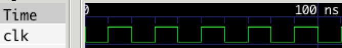
The state of a sequential circuit always changes with a clock pulse called the clock. The clock simply outputs a signal that turns “On” then “Off” over and over. The amount of time that it remains on and then off is determined by its period. The figure below shows a clock that has a frequency of 50 MHz (period = \(\frac{1}{50*10^6} = 20ns\)). The change of state for a sequential circuit can occur on the positive (rising) or negative (falling) edge of the clock. There is still propagation delay present in sequential circuits but it manifests itself in a different way. Instead of worrying about the longest path of your input signal, you must worry about the time it takes for the output to change once an input has been applied and the clock edge has occurred. This is called the clock to output time. Other important timing parameters you have to worry about are the setup time and hold time. These represent the amount of time you should hold an input prior to a clock edge and and the amount of time you should hold an input after a clock edge (respectively).
A real example
Let’s take a look at the timing parameters for for a real D type flip flop (i’ll talk more about this later) here: http://www.ti.com/lit/ds/symlink/cd74hc74.pdf. Timing parameters that we should care about start at the bottom of page 4. Again, these parameters are broken up into two categories: HC types and HCT types. This is for the same reason as last time: they are different implementations of the same thing. If you look closely, you can see that the HC types offer a range of voltages for operation including a low power option (2V) while the HCT types can only operate at 4.5V. The setup time and hold time for both types are the same at 4.5V (12ns and 3ns respectively). Their clock to output time is also the same at 4.5V (max of 35ns).
The Flip Flop
The most basic element of a sequential circuit is always a flip flop. There are a few different types of flip flops: T, JK, and D. The most used of these is easily the D Flip Flop. One look at the flip flops available from Digi-Key – the fourth largest electronic component distributor in North America – confirms this fact. At the time of me writing this article, there were 2,372 different types of flip flops available. 2,219 were D flip flops, 152 were JK flip flops, and sadly only 1 was a T flip flop. See for yourself here: http://www.digikey.com/short/341mvp. Needless to say, I will not be wasting time on discussing JK or T flip flops in detail.
D Flip Flops
The D flip flop takes the input applied to it on some clock edge and makes it the next output. The T flip flop only changes its output when the input is high, and the JK flip flop (which has two inputs J,K) changes based on specific encodings of the inputs (for instance, J=1 and K=0 will make the output 1 while J=0 and K=1 will reset the flip flop). The simplicity of the D flip flop is probably what makes it the most used type of flip flop.
The input of a D flip flop is usually called \(D\) and the output is usually called \(Q\). The truth table for a D flip flop is:
| \(Clock\) | \(D\) | \(Q_{next}\) |
|---|---|---|
| Edge | 0 | 0 |
| Edge | 1 | 1 |
| No Edge | X | Q |
As I said earlier, the edge of the clock is irrelevant because it can happen on the rising or the falling edge and it doesn’t change the truth table. Notice that the last entry in the truth table tells us that \(Q\) doesn’t change when there is no clock edge.
Below is an example of how to implement and simulate a positive edge triggered D flip flop with MyHDL. In this example I will declare two sets of signals: one with delays and one without delays. The delays will be for simulating the clock to output time and setup time. I will use the timing parameters from our real D flip flop example for these. Lastly, I will make it such that the simulation will change the input to the flip flop on the rising edge of the clock.
from myhdl import *

def dff(q, d, clk):
    """
    Postive edge triggered D-Flip Flop Module

    :param input d: input to flip flop
    :param input clk: clock signal
    :param output q: output of flip flop
    """
    @always(clk.posedge)
    def logic():
        # changes to d on the rising edge
        q.next = d
    return logic

def dff_testbench():
    """
    Testbench for D flip flop
    """

    """ declare signals """

    # clock signal
    clk = Signal(bool(0))

    # d flip flop input and output with delays
    d = Signal(bool(0), delay=12)
    q = Signal(bool(0), delay=35)

    # d flip flop input and output with no delays
    d_nd = Signal(bool(0))
    q_nd = Signal(bool(0))

    # instantiate D flip flop with delays
    dff_delay_inst = dff(q, d, clk)
    dff_nodelay_inst = dff(q_nd, d_nd, clk)

    @always(delay(50))
    def clkgen():
        """ clock generator """
        clk.next = not clk

    @always(clk.posedge)
    def stimulus():
        """ change input """
        d.next = not d
        d_nd.next = not d_nd

    return instances()

def simulate(timesteps):
    tb = traceSignals(dff_testbench)
    sim = Simulation(tb)
    sim.run(timesteps)

simulate(500)
<class 'myhdl._SuspendSimulation'>: Simulated 500 timesteps
Results
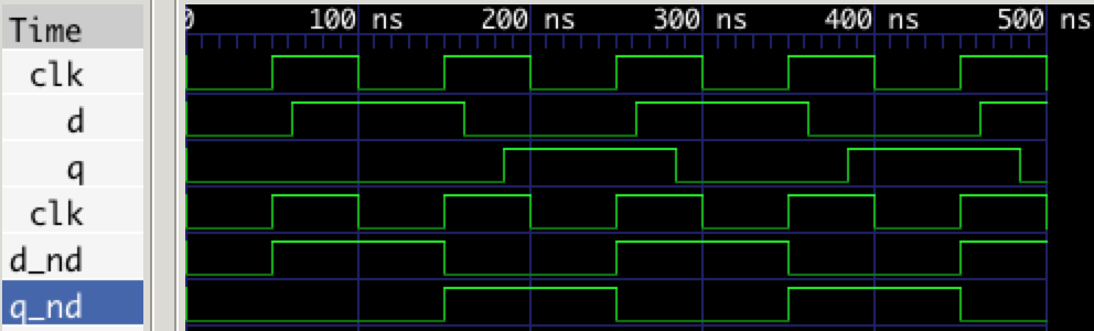
Notice that the delays are actually neglible and don’t impact the outcome of the simulation. That is to say, when \(D\) goes high on the first rising clock edge, \(Q\) stays low until the next rising clock edge where it then changes because \(D\) is high and this happens regardless of the delay. Therefore, my simulations will not have delays on the D flip flop inputs and outputs going forward.
What if the D Flip Flop was triggered on the negative edge? The results would simply be shifted further to the right on the timing diagram. I encourage you to modify the simulation and see this for yourself.
Hierarchy
There is a beautiful yet ugly approach to hardware development that shrouds this topic in obscurity: Abstraction. Elements like transistors, resistors, capacitors, etc. are used to construct digital circuits. If we wanted to simulate something like those, then we’d use a program like LTSpice. Once the behavior of the components that make up something like an AND gate are known, the next step is to abstract them away into a black box. This is where I believe people can get confused and/or lost. Combinational and sequential circuitry represents the lowest level of Hardware Description Languages. Combinational and sequential circuits are used to build modules that can then be used to then build other modules and so on. This structure represents the concept of a hierarchy but I like to think about it like a Matryoshka_doll. In MyHDL, “hierarchy can be modeled by defining the instances in a higher-level function, and returning them. This pattern can be repeated for an arbitrary number of hierarchical levels”\(^{[1]}\). This was done previously in the D flip flop example but now I will add another level to it in the example below.
Shift Register
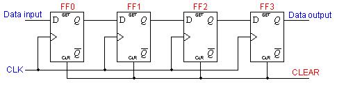
As an example of building hierarchy, we can chain together some D flip flops and make what is called a Shift Register. These devices are mainly used for converting between serial and parallel data. Serial data is data that is sent one bit at a time while parallel data is data sent many bits at a time. A Serial Peripherial Interface Bus is one such instance where converting between these two types of data is needed.
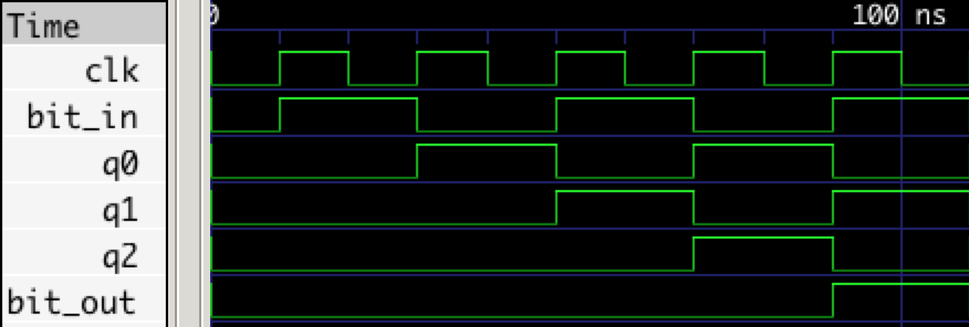
In particular, I will composed a 4-bit wide Serial In, Serial Out (SISO) Shift Regiser similar to the one depicted below. When a 1 is placed on the input of this device, it will take 4 clock periods for it to emerge on the output and the simulation results will confirm this.
from myhdl import *

def dff(q, d, clk):
    """
    Postive edge triggered D-Flip Flop Module

    :param input d: input to flip flop
    :param input clk: clock signal
    :param output q: output of flip flop
    """
    @always(clk.posedge)
    def logic():
        # changes to d on the rising edge
        q.next = d
    return logic

def shift_register(bit_out, bit_in, clk):
    """
    Serial-in, Serial-out (SISO) shift register

    :param input bit_in: input to SISO
    :param input clk: clock signal
    :param output bit_out: output of SISO
    """

    # internal signals that chain togeter DFFs
    q0, q1, q2 = [Signal(bool(0)) for i in range(3)]

    # instantiate D flip flops
    d0_inst = dff(q0, bit_in, clk)
    d1_inst = dff(q1, q0, clk)
    d2_inst = dff(q2, q1, clk)
    d3_inst = dff(bit_out, q2, clk)

    return instances()

def sr_testbench():
    clk = Signal(bool(0))
    din, dout = [Signal(bool(0)) for i in range(2)]
    sr_inst = shift_register(dout, din, clk)

    @always(delay(10))
    def clkgen():
        clk.next = not clk

    @always(clk.posedge)
    def stimulus():
        din.next = not din

    return instances()

def simulate(timesteps):
    tb = traceSignals(sr_testbench)
    sim = Simulation(tb)
    sim.run(timesteps)

simulate(500)
<class 'myhdl._SuspendSimulation'>: Simulated 500 timesteps
Results
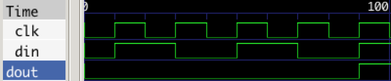
As expected, the simulation shows that it takes 4 clock cycles for a bit to propagate to the output of the circuit.
More advanced examples
This section contains some more advanced examples that I have laid the foundation for but will leave largely unexplained.
Linear Feedback Shift Registers (LFSR)
A linear feedback shift register are a particular type of shift register that is commonly used for generating random numbers. Here’s a really neat ipython notebook on the subject from one of the gentlmen at XESS Corp: https://github.com/xesscorp/CAT-Board/blob/master/tests/RNG_with_MyHDL.ipynb.
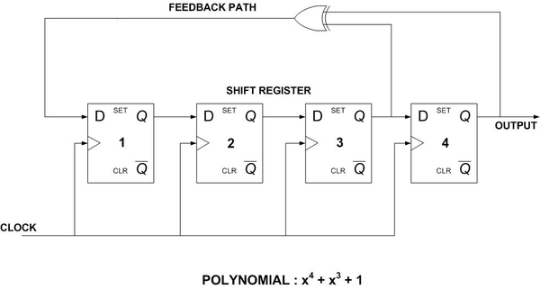
Below is an example of the implementation depicted in MyHDL.
"""
    4-bit Fibonaccio Linear Feedback Shift Register
    programmed using MyHDL library

    Programmed by William Harrington
    Website: wrh2.github.io
"""
from myhdl import *

def xor(y, a, b):
    """
    XOR function

    :param input a: first operand
    :param input b: second operand
    :param output y: a XOR b
    """
    @always_comb
    def logic():
        y.next = a ^ b
    return logic

def dff(q, d, clk):
    """
    D-Flip Flop Module

    :param input d: input to flip flop
    :param input clk: clock signal
    :param output q: output of flip flop
    """
    @always(clk.posedge)
    def logic():
        # changes to d on the rising edge
        q.next = d
    return logic

def LFSR(out, clk):
    """
    4-bit Linear Feedback Shift Register

    :param input clk: clock signal
    :param input seed: starting value, defaults to 0xF
    """

    """ internal signals declaration """
    d = Signal(bool(0))
    q0, q1, q2, q3 = [Signal(bool(1)) for i in range(4)]
    count = Signal(concat(q0, q1, q2, q3))

    """ module instantiation """
    d0 = dff(q0, d, clk)
    d1 = dff(q1, q0, clk)
    d2 = dff(q2, q1, clk)
    d3 = dff(q3, q2, clk)
    y1 = xor(d, q3, q2)

    @always(count)
    def output():
        out.next = count

    @always_comb
    def current():
        """
        This function creates bus from outputs of
        the D flip flops for easy viewing in a
        waveform viewer
        """
        count.next = concat(q0, q1, q2, q3)

    return instances()

def LFSR_testbench():
    """
    Testbench for linear feedback shift register
    """
    clk = Signal(bool(0))
    out = Signal(0)

    # instantiate linear feedback shift register
    lfsr_inst = LFSR(out, clk)

    """ clock generator """
    @always(delay(10))
    def clkgen():
        clk.next = not clk

    @instance
    def output_monitor():
        print "t(ns)\t output"
        print "--------------"
        while True:
            yield out
            print "%d\t %s" % (now(), bin(out))

    return instances()

def simulate(timesteps):
    tb = traceSignals(LFSR_testbench)
    sim = Simulation(tb)
    sim.run(timesteps)

simulate(300)
t(ns)	 output
--------------
10	 111
30	 11
50	 1
70	 1000
90	 100
110	 10
130	 1001
150	 1100
170	 110
190	 1011
210	 101
230	 1010
250	 1101
270	 1110
290	 1111


<class 'myhdl._SuspendSimulation'>: Simulated 300 timesteps
Asynchronous Circuits
The circuits so far have all been synchronous which means that they use the same clock signal. The examples below are asycnrhonous counters.
4-bit Asynchronous Up Counter
"""
    4-bit up counter. Count from 0x0 to 0xF.

    Programmed by William Harrington
    Website: wrh2.github.io
"""
from myhdl import *

def dff(q, nq, d, clk):
    """
    D-Flip Flop Module

    :param input d: input to flip flop
    :param input clk: clock signal
    :param output q: output of flip flop
    :param output nq: inverse of output
    """
    @always(clk.posedge)
    def logic():
        q.next = d
        nq.next = not d
    return logic

def up_counter(out, clk):
    """
    4-bit up counter using D-Flip Flops

    :param input clk: clock signal
    """

    """ internal signals """
    q0, q1, q2, q3 = [Signal(bool(0)) for i in range(4)]
    nq0, nq1, nq2, nq3 = [Signal(bool(0)) for i in range(4)]
    count = Signal(concat(q3, q2, q1, q0))

    """ chaining of d-flip flops """
    d0 = dff(q0, nq0, nq0, clk)
    d1 = dff(q1, nq1, nq1, nq0)
    d2 = dff(q2, nq2, nq2, nq1)
    d3 = dff(q3, nq3, nq3, nq2)

    """ makes bus from output of each d-flip flop """
    """ this is just for easy viewing of the count """
    @always_comb
    def keep_count():
        count.next = concat(q3, q2, q1, q0)

    @always(count)
    def output():
        out.next = count

    return instances()

def up_counter_testbench():
    clk = Signal(bool(0))
    out = Signal(0)

    up_inst = up_counter(out, clk)

    @always(delay(10))
    def clkgen():
        clk.next = not clk

    @instance
    def output_monitor():
        print "t(ns)\t output"
        print "--------------"
        while True:
                yield clk.posedge
                print "%d\t %s" % (now(), bin(out))

    return instances()

def simulate(timesteps):
    tb = traceSignals(up_counter_testbench)
    sim = Simulation(tb)
    sim.run(timesteps)

simulate(350)
t(ns)	 output
--------------
10	 0
30	 0
50	 1
70	 10
90	 11
110	 100
130	 101
150	 110
170	 111
190	 1000
210	 1001
230	 1010
250	 1011
270	 1100
290	 1101
310	 1110
330	 1111
350	 0


<class 'myhdl._SuspendSimulation'>: Simulated 350 timesteps
4-bit Asynchronous Down Counter
"""
    4-bit down counter. Counts down from 0xF to 0x0.

    Programmed by William Harrington
    Website: wrh2.github.io
"""
from myhdl import *

def dff(q, nq, d, clk):
    """
    D-Flip Flop Module

    :param input d: input to flip flop
    :param input clk: clock signal
    :param output q: output of flip flop
    :param output nq: inverse of output
    """
    @always(clk.posedge)
    def logic():
        q.next = d
        nq.next = not d
    return logic

def down_counter(out, clk):
    """4-bit down counter using D-Flip Flops

    :param input clk: clock signal
    """

    """ internal signals """
    q0, q1, q2, q3 = [Signal(bool(1)) for i in range(4)]
    nq0, nq1, nq2, nq3 = [Signal(bool(0)) for i in range(4)]
    count = Signal(concat(q3, q2, q1, q0))

    """ chaining of d-flip flops """
    d0 = dff(q0, nq0, nq0, clk)
    d1 = dff(q1, nq1, nq1, q0)
    d2 = dff(q2, nq2, nq2, q1)
    d3 = dff(q3, nq3, nq3, q2)

    """ makes bus from output of each d-flip flop """
    """ this is just for easy viewing of the count """
    @always_comb
    def keep_count():
        count.next = concat(q3, q2, q1, q0)

    @always(count)
    def output():
        out.next = count

    return instances()

def down_counter_testbench():
    # clock signal
    clk = Signal(bool(0))
    out = Signal(0xF)

    # instantiate down counter
    down_inst = down_counter(out, clk)

    """ clock signal generator """
    @always(delay(10))
    def clkgen():
        clk.next = not clk

    @instance
    def output_monitor():
        print "t(ns)\t output"
        print "--------------"
        while True:
            yield clk.posedge
            print "%d\t %s" % (now(), bin(out))

    return instances()

def simulate(timesteps):
    tb = traceSignals(down_counter_testbench)
    sim = Simulation(tb)
    sim.run(timesteps)

simulate(320)
t(ns)	 output
--------------
10	 1111
30	 1110
50	 1101
70	 1100
90	 1011
110	 1010
130	 1001
150	 1000
170	 111
190	 110
210	 101
230	 100
250	 11
270	 10
290	 1
310	 0


<class 'myhdl._SuspendSimulation'>: Simulated 320 timesteps
References
- http://docs.myhdl.org/en/stable/manual/intro.html#parameters-and-hierarchy
- Serial-in, Serial-out diagram from https://www.ee.usyd.edu.au/tutorials/digital_tutorial/part2/register02.html
- LFSR diagram from https://casper.berkeley.edu/wiki/Variable_Correlation_Digital_Noise_Source_for_FPGA